Building a UPDI flasher
The split-flap modules use an ATtiny1616, which is programmed over UPDI — a single-wire interface. You do not need a dedicated programmer. A cheap CH340 USB-to-TTL adapter with one Schottky diode soldered across two of its pins does the whole job, and the only tool you need is a soldering iron. This page shows the build and explains why the diode has to point one particular way.
Source: this is the flasher the firmware project itself documents in FLASHER.md. Once you have one, Flashing Modules covers putting the firmware on.
Parts
| Part | Notes |
|---|---|
| HiLetgo CH340 USB-to-TTL adapter | Sold as a 5-pack. Board marking HW-597, six-pin header 5V VCC 3V3 TXD RXD GND. Any CH340, CP2102 or FTDI adapter with the same pins works the same way. |
| 1N5817 Schottky diode | Any small Schottky diode does the job (1N5817, 1N5819, BAT85). |
| 3 jumper wires | Female-to-male. The female end plugs onto the adapter's header pins; the male end pushes into the holes of the module's UPDI header. They carry 3V3, GND and the UPDI line. |
| Soldering iron | For the one solder joint pair below. |
The full chain
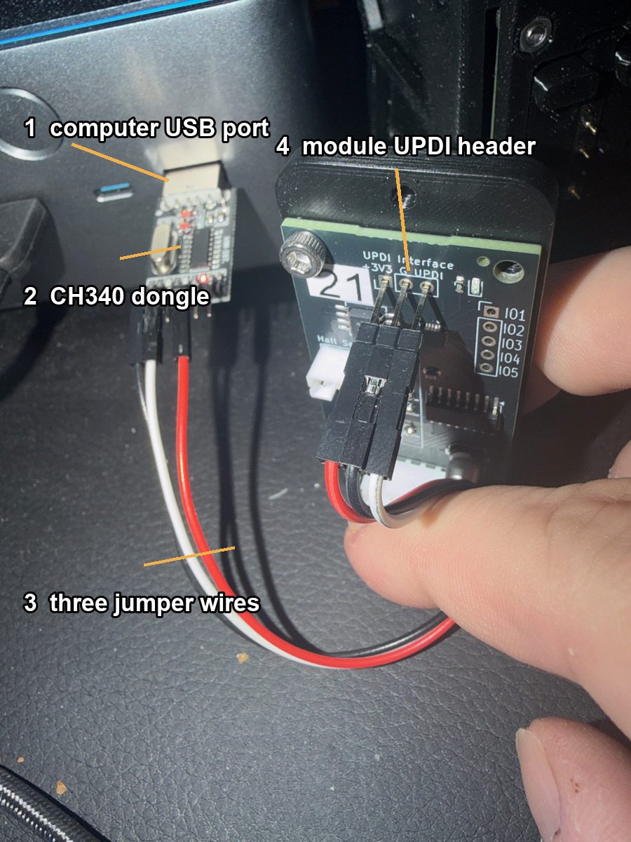
Computer → CH340 adapter in a USB port → three female-to-male jumper wires (female end on
the adapter, male end pushed into the module) → the module's UPDI Interface header,
which is labelled +3V3, G and UPDI. The adapter powers the module's controller
through the 3V3 wire while it is being flashed, so on the bench the module needs no
other supply — no 12 V, no rail.
The adapter
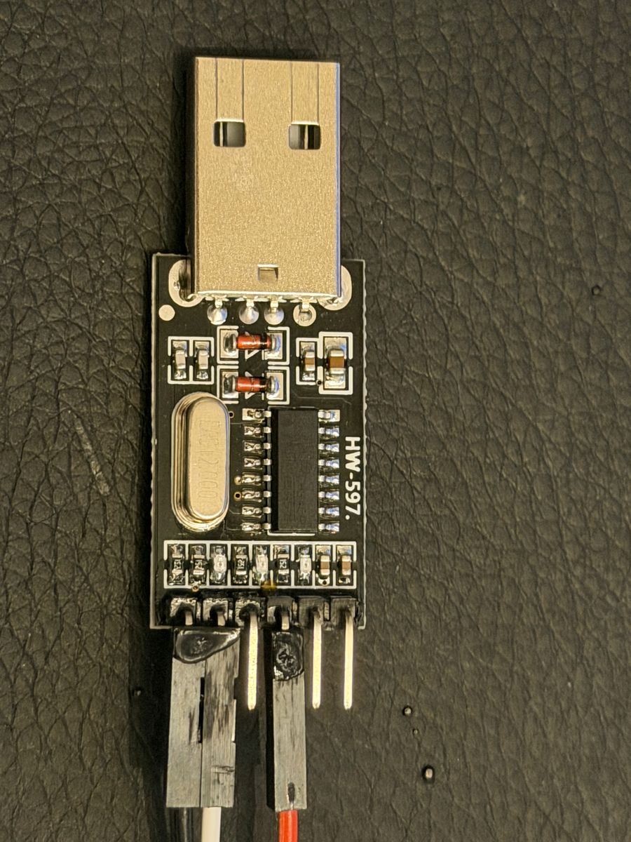
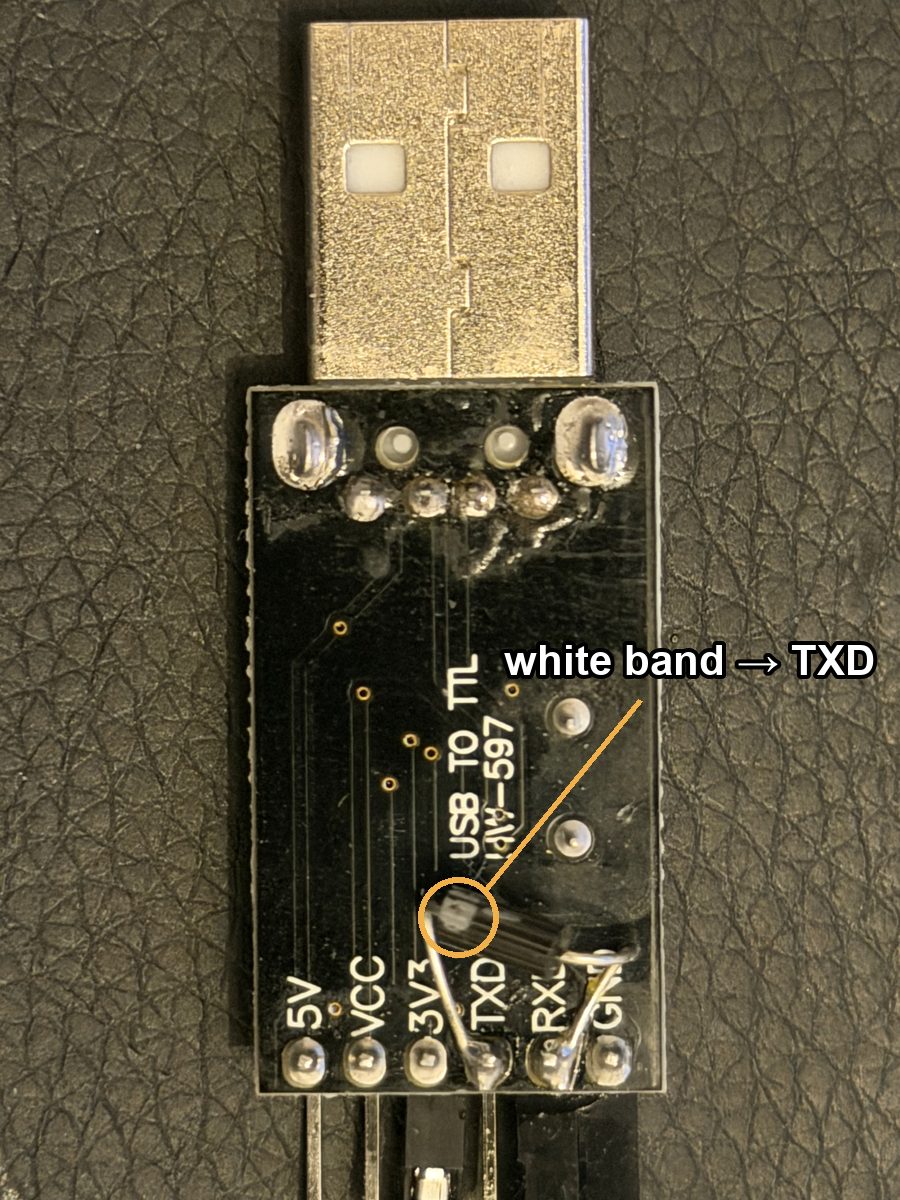
| Component side | Solder side |
|---|---|
 |
 |
Left, component side. Nothing here is modified. The jumper wires on the header run to the module.
Right, solder side. The one modification: a diode soldered between the TXD and RXD
pads, with its white band at the TXD end. That band is the whole point of this page.
Why one wire needs a diode
A serial adapter has two data pins: TXD talks, RXD listens. UPDI has one wire, and
both the programmer and the chip talk on it, taking turns. So the adapter's two pins have
to be joined into one line.
The ATtiny drives the UPDI line the polite way: it only ever pulls the line low, and
when it lets go an internal pull-up floats the line back high. The adapter's TXD pin is
not polite. It actively drives the line high whenever it is idle, which is most of the
time. Tie TXD straight to the UPDI pin and the moment the chip tries to answer by pulling
the line low, it is fighting the adapter's output. The answer is swamped and nothing works.
The diode turns TXD into a polite driver. With the diode's cathode on TXD, current can
only flow into TXD: when TXD goes low it pulls the shared line down through the
diode, but when TXD goes high the diode blocks and TXD is effectively disconnected. The
chip's pull-up holds the line high, and the chip can pull it low with nothing fighting
back. RXD sits on the shared line the whole time, so the adapter hears everything.
  CH340 adapter                                    module UPDI header

  TXD ───────|<───────┐
        band on the   │
        TXD end       ├──────────────────────────  UPDI   (pull-up inside the chip;
  RXD ────────────────┘                                    the chip only pulls low)

  3V3 ─────────────────────────────────────────── +3V3
  GND ─────────────────────────────────────────── G
Only RXD goes to the module's UPDI pin. Nothing connects to TXD except the diode.
Older guides (including an earlier version of this guide) described a resistor between
TXDandRXDinstead. A resistor works with some adapters and not others, because it only weakens the fight rather than ending it; the diode is the reliable build, and it is what the firmware'splatformio.iniis set up for.
Diodes are directional
A resistor does not care which way round it goes. A diode does; that is its entire job. It has two ends, an anode and a cathode, and it lets current flow from anode to cathode while blocking the other way. On the schematic symbol the arrow points from anode to cathode, and the bar at the arrow's tip is the cathode.
On the physical part the cathode is marked by a band printed on one end of the body. On the 1N5817 it is a white band on a black body. That band is the only thing telling you which way the diode faces, so before you solder, find it.
Solder the diode so the band is at the
TXDpad.¶Cathode (the banded end) to
TXD. Anode (the plain end) toRXD.
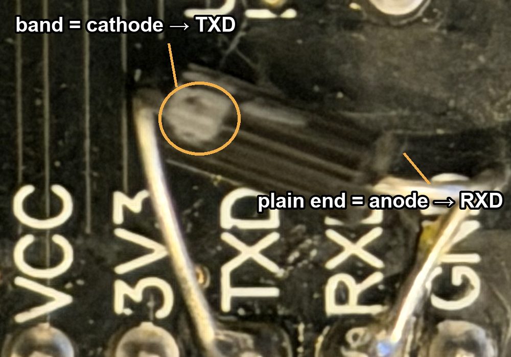
If you get it backwards the adapter can push the line high but can never pull it low,
so the chip never hears a single bit and avrdude stops with
UPDI link initialization failed. Nothing is damaged. Desolder the diode, turn it around,
and solder it again.
Soldering it
- Flip the adapter over. On the
HW-597the pads are labelled on the solder side, so you can readTXDandRXDdirectly. - Find the band on the diode. Bend the leads so the diode lies across the two pads with
the band end over
TXD. - Tin both pads. Solder the band lead to
TXD, then the plain lead toRXD. Trim the leads short so the diode lies flat. - Check that no solder bridges to the neighbouring
3V3orGNDpads.
Wiring it to a module
| Adapter pin | Module header pin | Purpose |
|---|---|---|
3V3 |
+3V3 |
Powers the module's controller while flashing. |
GND |
G |
Common ground. |
RXD |
UPDI |
The shared data line. |
TXD |
nothing | Only the diode connects here. |
If it says UPDI link initialization failed
- Check all three wires are seated at both ends. Without the
3V3wire the module has no power and cannot answer. - Give it a moment and try again. Some modules answer only a few seconds after being connected.
- Diode direction. The band must be at the
TXDpad. If it is atRXD, turn it around. - Try a slower speed —
28800baud instead of57600(upload_speedinplatformio.ini, or-b 28800for avrdude).
Next: Flashing Modules → — the two commands per module, with or without a compiler.